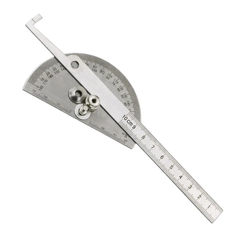
If the angle to be measured is formed on the left-hand side from the center of the protractor, we need to use the outer reading of the protractor.
Step 3: Decide which readings are to be followed. Step 2: Place the baseline of the protractor on the ray which is the base of the angle. Step 1: We first need to pIace the center (hole) of the protractor on the vertex O. Protractor angles how to#
Observe the following figure to know how to read a protractor and relate to the steps given below. Each inner reading and outer reading supplements each other, i.e., they add up to 180°. How to Read a Protractor?Ī protractor can be read using its inner readings or its outer readings depending on the angle that is formed. It has two readings - the outer reading and the inner reading that help to measure a given angle. Do not group them all together, just each hole with its corresponding box so we have three separate objects.A protractor is an instrument which is very easy to use.
The last, for all other intervals, set the hole to be 136mm long. Then, we will change one of the copies, for the intervals ending in 5, so that the hole is 134mm long. We will leave one of these pairs of objects alone, and we'll use that for the degree intervals of 10. Duplicate these shapes twice more so you have three sets total. Use the Align tool to center these objects to each other on the X and Y axes, and so they share lower Z limits. Make it 3mm tall (along the Z axis) and move its center so it is 1.5mm off of the workplane. Drag out another box and make it 130mm along the X axis. Drag out a box and make it 150mm along the X axis and 0.5mm along the Y axis. If you'd like to customize yours, refer back to step 8! 
I am making my demarcations 10mm long, 8mm long, and 7mm long, respectively. For ease of reading, we will make three styles of demarcation, one length for intervals of ten, a shorter length for measures ending in five, and the shortest length for all other measures. We now have a pristine protractor shape, but it isn't very useful without degree demarcations. Move the center of this box to -22mm on the Y axis.
To make a 15mm wide straightedge rule, divide the Y axis dimension of the box in half (74/2=37mm) and then subtract our desired dimension from this (37-15=22m). Make it larger than half of the new cylinder. Drag out a new box and center it to the origin along the X axis. My protractor is 150mm in diameter, so to make a 20mm wide rule, I need to subtract 20mm from 150mm, twice (150-40=110mm). Drag out a new cylinder and center it to the origin along the X and Y axes. I'll show you how I came to my measurements so, if you like, you can calculate your own. For instance, how thick do we want the straightedge rule and the protractor rule to be? I chose 15mm and 20mm, respectively, but you may make these features smaller, leaving more room for the window. We have an opportunity, now, to customize your protractor. We'll need a viewing window through which we read the lines when we are measuring. Since we are designing a protractor, this will be the point from which all measurements, while using the protractor, will radiate. If you click on the measurements along the X and Y axes and set them to Zero, your object will move to be perfectly centered on the origin. You'll now notice that the Ruler Helper measures from the origin to the center of the object. The text will then change to 'Use corner' which will let you know you are in midpoint mode. If you click this, it will change the mode. If you hover over the triangle, you'll see the text 'Use midpoint' appear. You'll notice a small triangle or arrow below the object, centered on its X axis. We don't need to worry about being precise in placement, the ruler helper will allow us to have fine grained control over the placement of objects. 
We will not be able to set the mode until we have placed an object on the workplane. Today, we'll be using the Ruler Helper in "Use midpoint" mode.Aligning this ruler helper to the major grid lines helps you make movement decisions faster. Grid lines are 1mm apart and major grid lines happen every 10mm. Make sure to align the axes of the ruler tool to a major (thicker) grid line. Drag the Ruler Helper so that its Origin is at the center of the Workplane.It is common with most tools, on a computer or in the real world, to set up the work environment, first, so everything you'll need will be at your disposal. Therefore, it is important that we begin with it in the right place. We will be making extensive use of the Ruler Helper, perhaps in ways you have not done before.


 0 kommentar(er)
